UDY
CYCLONE SAMPLE MILL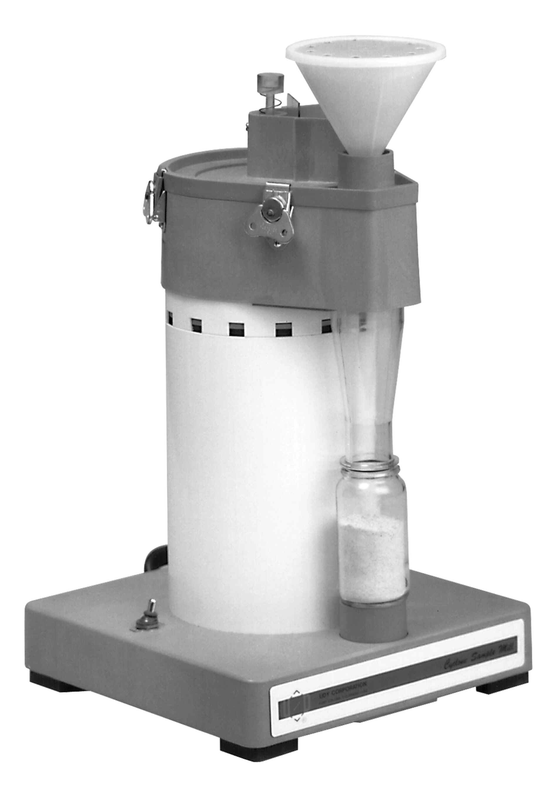
PRINCIPLES OF OPERATION
The Cyclone
Sample Mill uses a high velocity air-flow, an abrasive
surface, and centrifugal forces to grind material.
Figures 1 and 2 identify the main parts. The Impeller
rotates at a high speed creating the high velocity flow
of air to propel articles against the abrasive surface.
When material is added to the Mill, the rotation of the
Impeller and centrifugal force throw the particles to the
perimeter of the Grinding Chamber where the air-flow
pushes them along the abrasive tungsten carbide surface.
When the particles become small enough, they move with
the air-flow out of the Grinding Chamber and are
deposited in a sample Collection Bottle by cyclone
action.
The air-flow
prevents accumulation inside the Grinding Chamber
eliminating the need to clean out the Mill between
samples. The air-flow also minimizes heating of the
materials accumulation inside the Grinding Chamber
eliminating the need to clean out the Mill between
samples. The air-flow also minimizes heating of the
material to avoid thermal degradation.
The Mill creates a relatively uniform particle size. The
Screen only has an indirect effect on the particle size,
because most particles do not escape the Grinding Chamber
until they are small enough to flow with the air stream.
However, impact with the Impeller throws some larger
particles toward the Grinding Chamber exit. The Screen
provides an upper limit of the size particles that can be
thrown prematurely. Finer screens reduce the air-flow and
consequently, the particle size the air can carry, as
well as limiting the maximum particle size.
An optional Sample Feed Controller provides a uniform
feed rate of material into the Mill. This significantly
increases the uniformity of the particle size of the
ground samples. It also makes sample addition more
convenient and eliminates the possibility of Mill
overloading.
The Cyclone Sample Mill is available in Direct Drive and
Belt Drive versions. The Belt Drive version is
recommended for almost all applications. The Direct Drive
version can be used only for light duty application where
uniform particle size distribution is not needed. It uses
a .500 H.P. series wound universal motor with a speed of
about 10,000 to 20,000 rpm depending on the load. The
Belt Drive version is much quieter and has a higher
grinding capacity. It rotates the Impeller at a
relatively constant 12,600 rpm (10,500 for 50 Hz. Mills),
using a ¾ HP totally enclosed induction motor.
Additional general information about the Mill such as
materials millable, sample feed into the Mill, initial
and final particle sizes, etc. may be found in the color
brochure of the Mill.
Set-Up
Place the Mill
in the desired location. Verify that a screen and the
Cyclone Air Separator are in place, then place the Cover
on the top o the Mill. Secure the Cover by simultaneously
tightening two Clamps on diagonally opposite sides of the
Mill. Tighten the remaining two Clamps. Plug the Mill
into a suitable power outlet. Plug the Air Outlet Filter
Assembly (not used when using the Sample Feed Controller)
into the Cover outlet. If a Sample Feed Controller is to
be used, remove the Bin Gate and slide the Sample Feed
Controller Plate Mounting Plate into the Bin Gate slot.
Rest the motor on the top edge of the Sample Bin. Secure
the Sample Feed Controller by tightening the Bin gate Set
Screw. Plug the Sample Feed Controller into the Socket of
the backside of the Base (3010-017 and 301-018 models or
those newer models with the optional plug in the Base) or
into a separate power outlet.
OPERATION
Position a
Sample Collection Bottle under the Cyclone Body by
depressing the spring loaded Bottle Support. Then turn
the Mill on. DO NOT ADD SAMPLE BEFORE THE MILL IS TURNED
ON AND UP TO SPEED.
The first time material is ground or after changing types
of samples using the standard Cover without a Sample Feed
Controller, determine the proper Bin Gate position. The
Bin Gate should be positioned to prevent material from
entering the Mill fast enough to slow the Motor. Do not
dump sample into the Sample Bin only to prevent overloads
in case the sample is accidentally poured into the Bin
too fast.
Slowly pour the sample into the Mill from a small
container that holds the desired sample size. Do not
grind so much sample that it builds up in the Cyclone
Body with Bottle Seal above the Collection Bottle. The
standard 210 ml glass Collection Bottles hold up to 40
grams of wheat (approximately 50 ml before it is ground).
The maximum weight of other materials will vary. The
optional 500 and 1000 ml plastic Collection Bottles’
capacities have to be determined. Material will often
pile up in them and reach the Cyclone Body w/Bottle Seal
before completely filling the bottles. Gently tapping the
bottles can level out the material and permit grinding
larger quantities at one time. When using the optional
Nylon Collection Bag, it must be tied on securely to
avoid blowing out the sample. Position the Bag so that
the drawstring tightens about 1 to 2 cm above the end of
the Cyclone Body w/Bottle Seal; then wrap the string
around the Bag and the Cyclone Body w/Bottle Seal before
tying it.
When a Forage Cover is used to grind bulky low-density
materials, the materials must be added carefully to avoid
overloads. Pre-chopping the material and placing a large
Funnel on the Forage Cover is helpful. Funnels are
available through UDY Corporation or they can be
purchased from most hardware stores. The stem diameter
should be 38 mm or slightly less.
When a Sample Feed Controller is used, the sample is
dumped into the Hopper Funnel of the Sample Feed
Controller after the Mill is turned on. The power switch
on the Sample Feed Controller is ordinarily left on so
when the Mill is turned on, the Sample Feed Controller
also comes on (Models 3010-017 and 3010-018) of the older
models or with the newer models with the plug installed
in the Base.
DO NOT TURN THE MILL OFF UNTIL ALL THE MATERIAL HAS
EMPTIED FROM THE SAMPLE BIN AND THE SAMPLE FEED
CONTROLLER, IF USED, UNLESS A PROBLEM OCCURS.
If it becomes necessary to shut the Mill off before all
the material has fed into and exited from the Mill,
manual clean out of the Grinding Chamber may be required.
When the Sample Feed Controller is turned off with the
material in it, some may slowly leak from it and enter
into the Mill, especially the Mill is left on.
When no more sample appears in the Cyclone Body w/Bottle
Seal, the Mill can be turned off. If the Mill is to be
left running continuously, press the Air Inlet Plug
Assembly down momentarily while the Sample Collection
Bottle. Otherwise, dust will be expelled into the room.
However, do not block the air-flow through the Mill for
more than a few seconds.
Seal the Collection Bottle with a cap, then shake
thoroughly to obtain a homogenous sample mixture.
During the operation of the Mill, be alert for unusual
sounds and conditions. Problems are rare, but ones can
occur when can result in damage to the Mill. Heat
build-up caused by material under the Impeller or blocked
air-flow can ruin the Grinding Chamber. Alertness for
decreased air-flow or increased temperature of the
exhaust air is advised especially when grinding materials
which tend to build up in the Grinding Chamber.
GENERAL
INFORMATION
DO NOT OPERATE
THE MILL WITHOUT A SCREEN IN PLACE. THE GRINDING CHAMBER
WILL BE DAMAGED BY THE SAMPLE ABRASION.
IF THE MOTOR SLOWS DOWN, THE FEED RATE IS TOO FAST.
Excessive feeding will reduce the particle size
consistency and may result in material build-up in the
Grinding Chamber. NOTE: ON EARLIER MODELS OF THE MILL (60
HZ SERIAL NUMBERS BELOW 4000 AND 50 HZ MODELS WITH SERIAL
NUMBERS BELOW 2100) loading to the point of slowing the
motor down causes belt failure. Proper fee rate is
automatic when using a Sample Feed Controller of the
proper speed is used. Uniform feed rates lead to a more
uniform particles size and improved accuracy for NIR
analysis. Use of the Sample Feed Controller, is
therefore, highly recommended when possible, especially
if NIR instruments are to be used for testing. If a Mill
will no longer operate without slowing, when a Sample
Feed Controller is used, the Impeller or Grinding Ring,
or both, are probably excessively worn.
The maximum dimension of sample particles fed into the
Mill should not exceed 5 mm unless the particles are of
low mass such as leaves or forages. Large particles may
be reduced by a variety of means including crushing in a
bag with a hammer, blenders, coffee grinders, and other
special mills. Foliage leaves and stems may be fed
directly into the Mill when the optional Forage Cover is
used. Scissors or shears can be used to chop up long
pieces.
Larger quantities of material can be conveniently ground
and collected using the Nylon Sample Collection Bag (part
no. 30-0311) in place of a Sample Collection Bottle
connected to the lower portion of the Cyclone Body
w/Bottle Seal. Other bottles may be used with adapters or
by modifying the Cyclone Body w / Bottle Seal or Bottle
Support or both.
Occasionally, because of high moisture or oil content in
a product (typically 15% or more moisture or 20% or more
oil), or other properties of materials, the self-cleaning
action of the Mill may be hampered. In these cases,
additional air-flow through the Mill is recommended. To
increase the air-flow, a canister or tank vacuum cleaner
may be connected directly to the collar at the air outlet
in place of the Air Outlet Filter Assembly. Contrary to
the expectation, this will decrease sample loss and
improve performance because of the increased centrifugal
forces caused by the higher air-flow. However, this
slightly increases the average particle size.
When materials contain so much oil or moisture that
increasing the air-flow is not sufficient, grinding may
still be possible. Safflower seed, sunflower seed, meat
and bone meal, etc. can be ground in the Mill after a
pre-grinding with benonite clay or Filter Aid (Part no
30-0511)m an inert diatomaceous earth, if samples are not
being tested by NIR or other methods which might give
inaccurate results due to the added material.
Pre-grinding can be done in a blender. Typical ratios are
1 part sample with 2 to 3 parts absorbent. For
quantitative analytical work, the amount of absorbent and
the amount of sample must be weighed; the correct new
sample weight must be calculated. Multiply the usual
specified weight by the total weight of the sample plus
absorbent and divide by the weight of the sample.
To minimize the dust, a vacuum, other filters, or a vent
tube to another area can be connected to the air outlet
instead of the Air Outlet Filter Assembly. MAINTENANCE
The cover on the Air Outlet Filter Assembly should be
removed and the Air Outlet Filter Media is cleaned by
vigorous shaking or vacuuming whenever the air-flow
through the Mill is reduced. Obstruction of the air-flow
is also indicated by a significant warming of the air and
the loss of suction into the Mill.
After every 1,000 samples, or whenever samples begin
clinging to the surface, wipe the inside surface of the
Cyclone Body w/Bottle Seal with a cloth moistened with
Anti-static Solution (part no. 35-0505). Allow the
surfaces to completely dry before using the Mill.
If the Mill is turned off before all the material exits,
the Grinding Chamber must be cleaned out before the Mill
is restarted. Remove the Impeller and vacuum any material
accumulated under the Impeller. Be careful not to poke
the plastic seal of the bearings with a sharp object. DO
NOT clean the Chamber with liquids (If any liquid enters
the bearings, they will be ruined, and many liquids will
cause corrosion of the Grinding Ring).
If material is prone to collecting under the Impeller,
the feed rate may be too fast. If the materials collects
under the Impeller with slow feed rates, the Impeller is
defective and should be replaced.
The Screen, Impeller, and Grinding Ring are all subject
to wear and need periodic replacement. The frequency
depends on the abrasiveness of the samples and other
factors such as the type of testing being done on
samples. NIR testing generally requires replacement after
little wear to avoid calibration shifts. Screen need
replacement as they are worn away because the enlarged
holes permit larger particles to pass through them. The
vanes on the Impeller wear down (get shorter and outside
edges of the vanes become tapered like the edge of a
knife) (instead of rounded edges). Thus, the air-flow is
reduced. As air-flow is reduced, the grinding capacity is
lowered, and the samples must be added at a slower rate.
As the carbide abrasive ring (Grinding Ring) is worn,
additional time to mill the particles and the grinding
capacity is lowered.
Typical lifetimes for the Screen, Impeller, and Grinding
Ring area are approximately 2000 to 3000; 6000 to 9000;
and 12000 to 18000 samples of weight, respectively. The
ratio of using up to three screens for each Impeller and
three Impellers for each Grinding Ring is common; but
there are significant exception for other types of
samples. Some forges are abrasive enough to wear out both
the Screen and the Impeller after several hundred
samples. Having spare parts available to permit
comparison of old and new components (to show degree of
wear) as well as for back-ups in case of a rock or other
foreign debris damages the parts. Having spare parts on
hand can also prevent shut-downs.
The Impeller is replaced by loosening the set screw
holding it in place on the Drive Bearing Shaft. Be sure
the replacement is firmly seated with the top of the
Impeller flush with the top of the Drive Bearing Shaft
and the set screw fully tightened into the flat of the
Drive Bearing Shaft. DO NOT OVERTIGHTEN.
INSTALLATION OF THE DRIVE BELTS
The Drive Belts
are designed to give years of service, even with severe
overloading. Spares are not recommended since unused
belts may deteriorate nearly as fast as the ones in the
Mill. Do not apply belt dressing. If a Mill is used in a
critical operation, having a spare set of belts may be
advisable, especially after belts are several years old.
Should it become necessary to change your drive belts,
replacement is as follows:
| 1. |
Turn the
Mill off and unplug the electrical cord from the
wall receptacle. |
| 2. |
Remove the
two small screws (8-32 x ¼ phillister head)
holding the Belt Access Ring in place. Loosen the
nuts on the bottom of the Mill, if necessary, to
free the Belt Access Ring. |
| 3. |
Slip the
Belt Access Ring down and lay the Mill on its
side. |
| 4. |
Tighten
the Belt Tension Release Screw clockwise to
release tension on the belts. Do not attempt to
tight the screw further after a strong resistance
is felt. |
| 5. |
Remove
both old belts and install both new drive belts.
Forceps and other similar tools are helpful in
doing this. Make sure the Drive Pulleys are clean
(if the old belts overheated). Do not use grease
or chemicals. BELTS MUST BE CHANGED IN MATCHED
PAIRS. The ridged side of the Joined Belts must
be facing out. |
| 6. |
Fully
loosening tensioning screw to tighten the belts.
Full tension is being applied if the head of the
screw begins moving out, away from the Mill. |
| 7. |
Replace
the Belt Access Ring. |
Bearing failure
is rare although some types of samples such as forages
cause more frequent failure. The Bearings are sealed and
should not be oiled or have greased applied. Oil and
grease will accumulate dust and accelerate failure. If
the Drive Bearings are making noise or running abnormally
hot, they must be replaced or the Grinding Chamber will
be damaged. Do not replace the Drive Bearings with ones
obtained from any other sources than UDY Corporation.
They are special bearings and the complete manufacturers
code is not represented on the bearings. Installing
bearings other than those obtained through UDY
Corporation will void the warranty, if the unit is under
warranty. Special tools are also required for
installation of the bearings. Improper installation of
the Drive Bearings will cause damage. Replacement
bearings on the shaft are available through UDY
Corporation. Installation instructions are also included.
The replacement of the Drive Bearing Assembly is not
difficult for skilled repair-persons.
The replacement requires Ring Pliers and measurement of
the Pulley spacing (tool available) to within 0.1 mm
(0.004”). Repair at UDY Corporation is recommended,
however, because it provides an opportunity for
knowledgeable and thorough examination of the Mill.
Belt tensioning assembly and motor failures are best
serviced by UDY Corporation. Repaired and updated Mills
function like new. Our repair rates are very reasonable
encouraging frequent maintenance.
Spare parts that
are recommended: Screen(s), Grinding Rings, Impellers 8
mm, Sample Collection Bottles 120 ml, Anti-static Soln,
and Air Outlet Filter Media.
INSTALLATION OF THE GRINDING RING
ALWAYS TURN YOUR MILL OFF AND DISCONNECT FROM THE
ELECTRICAL SOURCE
| 1. |
Remove the
Cover and the Impeller from the Mill. |
| 2. |
Remove the
old Grinding Ring by bending it in toward the
center of the Grinding Chamber. Start at the seam
opposite the sample outlet. |
| 3. |
Clean out
all the sealant residue. |
| 4. |
Apply a
small bead of (approximately 2 –3 mm) of
100% silicon sealant (obtained from your local
hardware store) or caulking around the perimeter
of the Grinding Chamber. DO NOT USE ADHESIVE.
Spreading it out in a thin layer is suggested,
but not required. |
| 5. |
Position
the Grinding Ring so that the seam side is
approximately 1-3 mm into the Grinding Chamber
and the offset for the Screen is lined up with
the offset in the Grinding Chamber. Note that the
top edge of the Grinding Ring is indicated by
arrows on the Grinding Ring. |
| 6. |
Push the
Grinding Ring from both sides of the outlet
opening to shape the Grinding Ring and get it
started into the Grinding Chamber. Support the
Mill so the Grinding Ring can be pressed toward
the seam and into the Grinding Chamber without
the Mill moving. Be careful to not distort the
Grinding Ring near the sample outlet. The
Grinding Ring will seem too long, but it is not. |
| 7. |
Verify the
outlet opening is properly aligned. If not,
remove the Grinding Ring and adjust its position.
After the Grinding Ring is started into the
Grinding Chamber and aligned, remove the tape (on
the Grinding Ring) joining the seam. |
| 8. |
Using a
rubber mallet or a wooden block and hammer,
GENTLY, tap the Grinding Ring all around to press
it down into position. Use care to have it go
straight down into position. When it is all the
way down into position, the top edge should be a
uniform very small distance above the top of the
Grinding Chamber or flush with it. DO NOT use a
metal hammer directly on the Grinding Ring since
dents and rough areas on the Grinding Ring will
result in leaks where the Cover “O”
ring is and will not seal properly. |
| 9. |
Remove any
excess sealant. It may be easier to wait until it
sets and then peel it away (especially it there
is an excess). The sealant must set before the
Mill is placed in operation. |
| 10. |
Install a
screen. If necessary, shape the sample outlet so
that a Screen will slip down into the slot
between the Grinding Ring and the Grinding
Chamber outlet opening. Screens must not extend
higher then the Grinding Ring. |
| 11. |
Check the
top edge of the Grinding Ring for rough spots and
carbide particles. If there are any, remove them.
Carbide particles should scrape off fairly
easily. A file may be used. Do not remove enough
material to make the top edge of the Grinding
Ring lower than the top surface of the Grinding
Chamber. |
| 12. |
Replace
the Impeller and the Cover. |
|